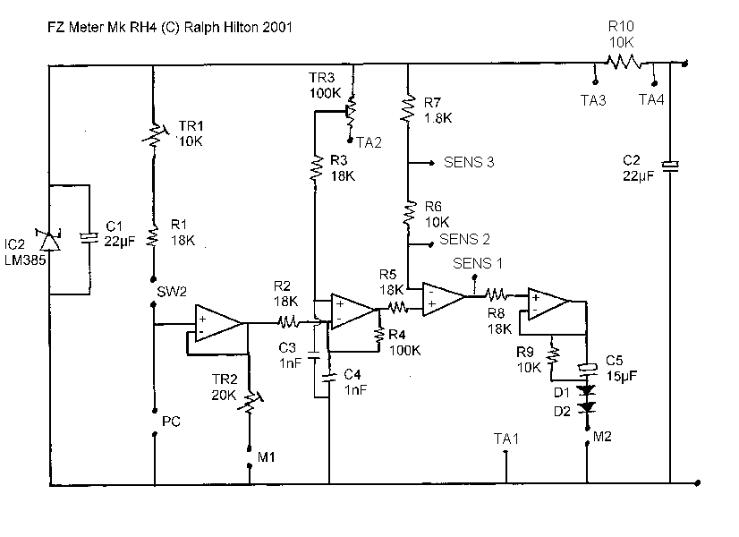
1. The voltage reference for
the bridge circuit is simplified.
2. The meter biasing has
been adjusted to use a standard 0 - 100ľA meter rather then the custom
movement required in the Mk2.
3. The circuit now uses
a readily available LM324 op amp rather than the more expensive and sometimes
hard to obtain OP420.
4. The circuit includes
amplification for the meter speed making it possible to use an off-the-shelf
movement rather than a custom made high speed one.

The diodes are any silicon
signal diode. The LM385 should be a 1.26 volt low power version.
The circuit is powered by 3 AA or AAA cells giving 4.5 volts.
The circuit can be used
for 1 or 2 meter movements. If one just uses 1 meter then TR2 is omitted
and the high end of the TA pot goes to the point marked TA3. For a dual
dial meter a multiturn pot can be used. If a 3 turn pot is available then
connect the high end to TA3. If only 10 turn is available then try TA3 and
TA4 to see which works best for you.
The TA pot should be 20k
wirewound such as Bourns 3590S-2-203 and the sensitivity pot 50k.
For normal use with 2 cans
SW2 can be shorted. If one wants automatic retrimming for solo cans or fingertip
electrodes then switch in values of 22k and 39k respectively.
Calibration:
1. Adjust the mechanical
zero of the TA meter to 1/20th division below zero. I.E. 0.95 TA.
2. Adjust TR2 so that the TA meter reads 6.5 with no connection to the
meter.
3. Connect a 12.5K resistor and adjust TR1 so the the TA meter reads 3.0
4. Short circuit the PC input and adjust TR3 so that the needle is on the
dial with the TA pot all the way anti-clockwise.
A suitable meter movement
is available at
http://www.sew.com.tw/st-150.htm
The scales for the meter
movements can be created using the program here.
I would use a taut band movement.
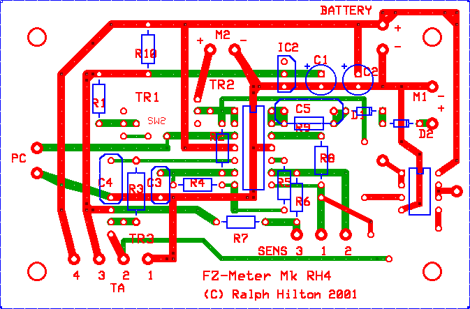
The printed circuits boards can be made up by www.expresspcb.com Software can be downloaded from their site and boards ordered online. Here is the pcb layout in their format.

Photos